Intelligent Completions
1 Introduction
Among the key motivations for intelligent well technologies have been:
This technology encompasses two primary concepts:
The first implementation of intelligence in completions began in the late 1980s, with the installation of pressure-temperature gauges to give real-time readings of well bottomhole pressure. Prior to development of interventionless technology in the late 1990s, zone flow could only be modified with rig intervention or by coiled-tubing-conveyed methods of perforating, squeezing, or shifting a sleeve.
This document summarizes some of the current vendor capabilities. It is not necessarily comprehensive.
2 Baker Oil Tools
Baker Oil Tools offers:
Baker Oil Tools began work on intelligent flow control in 1995. A joint venture with Schlumberger was created in 1997 to develop an all-electric intelligent system (InChargeTM). As a separate, independent project, Baker Oil Tools developed a hydraulically actuated system (InForceTM) based on its CM Sliding Sleeve. The Schlumberger joint venture was dissolved after the Baker Hughes merger with Western Atlas in August 1998. After that time, Baker Oil Tools and Schlumberger pursued intelligent well system (IWS) development separately.
Baker Oil Tools continued both the all-electric and hydraulic development projects. InForceTM the company’s first hydraulic intelligent system, was introduced commercially in 1999. InCharge,TM the company’s first all-electric system, was introduced in the second half of 2000.
2.1 Hydraulically Actuated Intelligent Completions:
Many individual land and platform wells have been completed in up to 20 pressure-isolated intervals (typically stacked-gas sands). Historically, these wells have used sliding sleeves between isolation packers to selectively access/shut-off individual zones. These mechanically actuated sliding sleeves required slickline or coiled-tubing through-tubing intervention to shift them opened/closed.
During the 1960s and 1970s, significant investment and efforts resulted in the development of hydraulically controlled, ‘fail-safe’ surface-controlled subsurface safety valve safety systems for use in hazardous environments and/or environmentally sensitive areas. These safety valves contain an integral hydraulic actuating cylinder, which controls the binary (open/close) position of a closure member (usually a flapper- or ball-type valve). However, their function confined them to a shallow location within the wellbore (~100 meters sub-mudline).
For wellbores accessing multiple zones, sliding sleeves are used for zonal isolation and selectivity, flow shut-off, commingling production, and transient testing. They are typically placed in the tubing string. Hydraulically actuated sliding sleeves offer fullbore access and provide an economic and reliable alternative to more complex, integrated intelligent completion systems when only open/close functionality is desired.
Traditional use of conventional sliding sleeves requires intervention to mechanically shift the sleeve insert. In an intelligent completion system, by combining real-time data monitoring with a remote-controlled hydraulic sliding sleeve, intervention can be avoided. This is especially the in high-angle, extended-reach and multilateral wells on land or in offshore, dry-tree platform environments. In addition, a surface-controlled hydraulic sliding sleeve allows an operator access to zones below an electric submersible pump.
A hydraulically based, intelligent completion system primarily consists of hydraulic sliding sleeves and feed-through isolation packers. The hydraulic sliding sleeves are remotely operated from the surface using dedicated hydraulic control lines. The feed-through packers accommodate the control lines that are necessary to operate the hydraulic sliding sleeves and the permanent downhole gauges. All hydraulic control lines and monitoring equipment are integrated into the system with the appropriate encapsulation and protection.
2.2 InForceTM Hydraulically Actuated System:
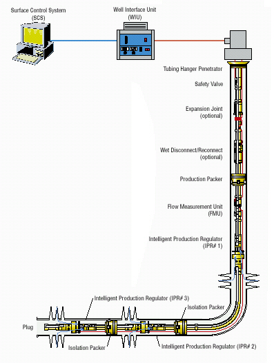
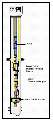
“The InForce Intelligent Well System uses Baker Oil Tools’ HCMTM remote-controlled hydraulically actuated sliding sleeves, isolation packers, and downhole permanent gauge monitoring to achieve remote flow control and to shorten detection and response times.”
|
|
Multi-feedthrough packers accommodate control line passages to allow multiple sliding sleeves. On-off shutoff is remotely operated from surface via two dedicated hydraulic control lines for each sleeve. "These connect to a balanced hydraulic chamber that actuates an inner sleeve. Pressure is applied to the open line, while the surface valve on the return line remains open to the hydraulic reservoir. Once shifting pressure is satisfied, the inner sleeve begins to travel, exposing equalizing slots momentarily until the valve is fully open. To close the sleeve, pressure is applied to the return line while the open line surface valve remains open to the hydraulic reservoir." This provides a positive indication of whether the sleeve has successfully closed or opened. Control line bypass protection on the hydraulic sliding sleeve is created with a protective cover plate that protects up to six 1/4" control lines from side load and flow erosion, and allows multiple sleeves and gauges to be positioned below the top and subsequent sleeves. Hydraulic control can be manual or automated, using valves and actuators. |
Permanent downhole quartz gauges send real-time pressure and temperature data to a PC-based surface system that monitors each zone. A single electrical conductor penetrates the wellhead and provides power and communications to each gauge.
2.3 An Example:
|
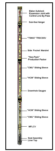
The dual-zone InForce system was installed on the Snorre P-30 well. The well's total measured depth is 21,648 ft (6,600 m) with the remote controlled zones being between 15,600 ft (4775 m) to 17,056 ft (5,200 m); a vertical depth of approximately 8,900 ft (2,700 m), and inclination of 80° at the reservoir. The system controls reservoir flow from two zones within the 9-5/8-in. casing. The remaining flow is not remotely controlled and is delivered from a perforated 5˝" liner to TD. The dual-zone completion was installed with a 13 ppg (1.56 SG) oil-based mud across the perforations and heavy brine from perforations to surface. The isolation of the individual intervals was accomplished by using two 9-5/8-inch retrievable feed-through packers that incorporate a feature to allow bypass of the control lines while providing for proper barrier requirements. Six control lines accommodated two HCM remote controlled hydraulic sliding sleeves, one tubing/annulus temperature and pressure gauge, and one tubing-retrievable safety valve. The HCM sleeves were actuated five times during the well initial cleanup and flow tests. The Snorre project was the first installation of Baker's InForce system in the North Sea. Systems were successfully installed in the Middle and Far East in 1999. Those systems' abilities to remotely open and close sliding sleeves repeatedly and reliably, within expected time frames, have significantly reduced the time, costs, and risks associated with conventional mechanical sleeve actuation. |
An InForce Schematic
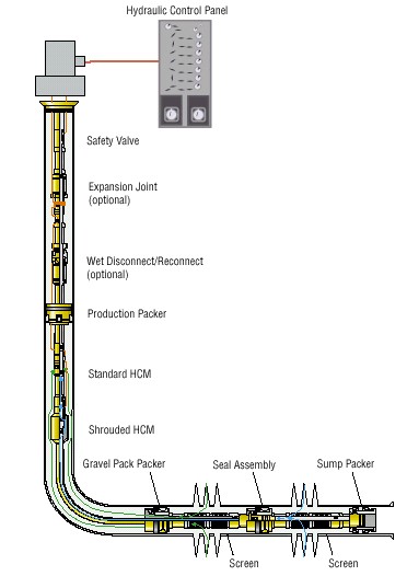
An InForce System |
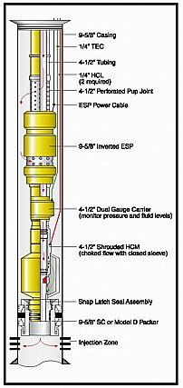
Inverted ESP |
Dual-Zone Producer |
| InForce TM | 7 in. x 3-1/2 in. | 9-5/8 in. x 4-1/2 in. | 9-5/8 in. x 5-1/2 in. |
| Maximum Temperature (° C) | 163 | 121 | 121 |
| Maximum Pressure (psi) | 7,500 | 7,500/5,000 | 6,300/5,000 |
| Minimum ID (in) | 2.750/2.812 | 3.688/3.750 | 4.313/4.562 |
| Zones | 3 | 3 | 3 |
| Number of Surface Penetrations | 4 | 4 | 4 |
| Materials | 13 Cr, Inconel 718, 440 | 13 Cr, Inconel 718,4140 | 13 Cr, Inconel 718, 4140 |
| Shrouded Version? | Yes | Yes | No |
| Maximum Actuator Force (lb) | 12,900 | 12,000 | 17,136 |
2.4 InChargeTM
InChargeTM is the first intelligent completion system to use electrically powered and controlled valves and infinitely variable chokes. The system monitors pressure, temperature and flow at the formation face level(s) in both tubing and annulus. The system's infinitely variable chokes allow selective control of injection rates into individual zones.
The InChargeTM system incorporates the world's first electrical downhole wet disconnect anchor system. This system simplifies maintenance and repair in the upper portion of the completion string through an electric umbilical to the surface that can be repeatedly disconnected and re-connected.
The InChargeTM system (7in. x 3 ˝ in. and 9 5/8 in. x 5 ˝ in.) is equally applicable to vertical, deviated and horizontal wells, completed on land or offshore, from platforms or subsea. One aspect of the InCharge system that is particularly valuable to subsea operators is the single control line that penetrates packers and wellhead. Power transmission, command and control, and data transmission are combined in a single, Ľ-inch penetration. From this control line, the operator can monitor and control up to 12 zones in a single well, and up to 12 wells from a single InChargeTM Surface Control System.
Another positive feature of the system is its power-on-communications architecture that requires little to no retrofit of existing subsea trees.
| InForce TM | 7 in. x 3-1/2 in. | 9-5/8 in. x 5-1/2 in. |
| Maximum Temperature (° C) | 125 | 125 |
| Maximum Pressure (psi) | 7,500/10,000 | 6,300 |
| Minimum ID (in) | 2.750/2.812 | 4.313/4.562 |
| Zones | 12 | 12 |
| Number of Surface Penetrations | 1 | 1 |
| Materials | 13 Cr, Inconel 718 | 13 Cr, Inconel 718 |
| Shrouded Version? | Yes | No |
| Maximum Actuator Force (lb) | 6,000 | 10,000 |
With the infinitely variable choking, zones can be choked incrementally open or closed to maintain optimum flow and prevent cross-flow. In the case of a required well shut-in, each zone can be shut in immediately to prevent crossflow that could occur if the zones remained open during a surface shut-in.
With permanent real-time downhole pressure measurement capability, pressure transient tests can be obtained as needed.
2.5 An Example
The InCharge system was deployed in an onshore well in preparation for a subsequent subsea installation, and is remotely monitored through a satellite link from Petrobras' operational base in the city of Natal, 200 miles from the well site. The InCharge system is ultimately intended for Campos Basin deepwater installations.
2.6 References
3 Halliburton
Halliburton's SmartWellTM systems are also remotely operated adaptive completion systems. It is possible to reconfigure a well's architecture at will and acquire real-time data without well intervention. SmartWellTM completions allow for managing downhole sensors and flow control devices in real-time via an umbilical from the surface. A SmartWellTM system will be able to determine flow rates, water cut, GOR and fluid composition from each zone, commingle production from separate reservoirs, optimize artificial lift efficiency and control production from, or injection into, zones with varying permeability.
The SCRAMSTM (Surface Controlled Reservoir Analysis and Management System) is a fully integrated reservoir management system consisting of both downhole data acquisition/ flow management and surface control and data links. To date, at least fourteen SCRAMS® systems have been installed throughout Norway, the Gulf of Mexico, the Adriatic Sea and Nigeria. The system could consist of some of the following components:
3.1 Design Data
| Size | ...................... | 3 1/2" tubing |
| Maximum O | ...................... | 5.81" |
| Minimum ID | ...................... | 2.750"/2.813" |
| Thread Connections | ...................... | 3 1/2" 9.2 lb New VAM |
| Maximum Differential Pressure | ...................... | 7,500 psi | Maximum Absolute Pressure | ...................... | 12,500 psi | Material | ...................... | Inc925/13Cr/Tungsten Carbide | Other Sizes | ...................... | Also available in 9 5/8-inch casing x 5 ˝-inch tubing size. |
Direct Hydraulics and Mini-Hydraulics are also technologies available to the industry through WellDynamics. Direct Hydraulics is a more conventional system - its major attraction is the ability to control large numbers of devices without having large numbers of wellhead penetrations. More than 20 systems have been installed in the North Sea and the Middle East. Mini-Hydraulics is appropriate where low cost is an absolute requirement, with a single hydraulic line being required to operate each downhole device. More than 15 systems have been installed throughout the Far East and South America.
3.2 Mini-Hydraulic System
The Mini-Hydraulic System provides a means to control downhole flow control devices with more than one operating mode or position with a single hydraulic line dedicated for each device. Tools that may be adapted for use with this system include tubing-mounted ball valves and sliding sleeves. The Mini- Hydraulic system can also be used with devices constructed with two-way piston (open/close) actuators to provide force in either direction in response to differential pressure across the piston. Other fail-safe devices based on biasing springs such as SCSSVs typically provide only a few hundred pounds closing force at setting depth. By their nature, these devices can only be set to default in one particular position upon loss of control line pressure, and they have depth limits that render them unusable for operating devices at TVD in many wells. The Mini-Hydraulic system provides for substantial operating forces in the range of 10,000 to 20,000 lb for driving the device in both directions. High driving forces mean more reliable operation when environmental conditions such as scale and corrosion might increase frictional forces over time. The system may be adapted for use at any practical setting depth.
Digital Hydraulic System
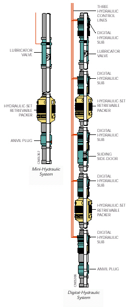
The Digital Hydraulic System is a closed-loop, all-hydraulic well control system that uses digital (binary) code placed on the hydraulic lines to command a suite of downhole tools. The digital hydraulic concept uses the logical presence of pressure or the logical absence of pressure to communicate between the surface controller and the downhole tools. The precise pressure level or time for which it is applied is not important (within the operational limits). Based on this concept, PES has designed a system, which is simple to operate yet gives reliable command and communication to a large number of tools while minimizing the number of control lines. A three-line digital hydraulic system is capable of independently controlling up to six double acting devices. These devices would typically be of two basic forms, either an on/off interval control valve or a variable interval control valve. The addressing of a six-zone system is the same for both valve types; however, controlled incremental movement of the variable ICV requires greater control over surface pressures than when operating an on/off ICV.
WellDynamics also offers very fine control of the IVICVTM, with an advanced option, known as the AccuPulseTM accumulator system, which accumulates, then dispenses a fixed known quantity of hydraulic fluid downhole, enabling an operator to adjust the Flow Control Device precisely in defined increments. The major benefit of this are that the full hydraulic force is always being applied to the downhole device in both opening and closing directions. This is critical for reliable device operation in hostile downhole environments where debris and scale can obstruct device operation.
This AccuPulseTM accumulator system overcomes the difficulty of adjusting variable position devices at the end of many thousands of feet of hydraulic line - fluid compressibility and temperature variations generally make this difficult.
|
|
 |
Standard Radial Flow Version |
Shrouded Version for Inline Flow Applications |
Examples:
The first installation of SCRAMSTM SmartWell technology took place in the Norwegian North Sea in 1997. Anticipating a gas breakthrough in one of the reservoirs in a well in its Snorre Field, SAGA Petroleum installed a system so it could choke back production if a breakthrough occurred. The technology performed as anticipated.
Since then, SCRAMSTM has been installed in at least 10 more wells, at least four of which are subsea, and including such operators as AGIP, Norsk Hydro, Maersk, Statoil, and British Borneo. For example, Maersk, operating in a field in the southern sector of the North Sea, is using the technology to manage the injection of fluid into multiple zones to maintain reservoir pressure. In addition, Norsk Hydro employed SmartWell technology to help extend the life of the huge Oseberg Field in the Norwegian North Sea.
As indicated, Maersk has experience with a SCRAMS installation in one of its North Sea injection operations. Three discrete zones were designed for, as shown in Table 1.
Table 1. SCRAMS Choke Design
| Zone | Rate (BWPD) |
Chokes |
| 3 | 7,000 | 15 and 20 mm |
| 2 | 5,000 - 7,000 | 12 and 17 mm |
| 1 | 2,000 | Fixed 8 mm |
Each zone was designed as a fractured situation. Planned intake into each zone was planned for and regulated on the basis of zonal pressure and estimates of the fracture size. The fracture size was inferred by using a Koning-type fracture model and pressure falloff survey interpretation, when that was available.
The system has been operating successfully. Table 2 shows the partitioning of flow into each zone as a consequence of choke adjustments during September 1999. The access to Zone 2 was increased in September 1999 and the percentage of flow going into that zone increased according.
Table 2. SCRAMS Choke Design
| Zone | Percentage of Overall Flow in Each Zone | |
| Before September 1999 Zone 2 ---1/3 open Zone 3 ---2/3 open |
After September 1999 Zone 2 ---2/3 open Zone 3 ---2/3 open |
|
| 3 | 65 | 52 |
| 2 | 24 | 37 | 1 | 11 | 11 |
4 Sintef
The first intelligent well system, the so-called SCRAMS system1, was brought to market in 1996, and in August 1997 was first installed at Saga's Snorre TLP in the North Sea. A schematic of this completion is shown in Figure 1. Other installations have followed. Generally, these completions include remotely controlled downhole valves with zonal isolation and monitoring functionality.
"But, as with most new technologies, there have been teething problems. While some installations have been relatively successful, others have been less flourishing. A number of system failures have been encountered during or shortly after completion of most of these wells as may be seen in the status overview of installations as of May 2000 (Table 3)."
"Manufacturers are still struggling to develop and prove 'sufficient' reliability of their most sophisticated intelligent well systems; operators are therefore very reluctant to fully embrace the new technology although some of the potential benefits clearly have been demonstrated. Operators are concerned with the higher initial investment and the poor reliability that has been reported from the first few installations. It has, however, been demonstrated that the higher initial investment actually has paid off despite rather poor system reliability."
Table 3. Status Overview of Intelligent Well Installations (as of May 2000)
| System | Experience |
| SCRAMS:Ten installations with a total of 26 inflow control valves. The number of inflow control valves per well varies from one to four. |
|
| Others:These are hydraulically operated valves with separate instrumentation. One of the installations had three valve units. |
|
4.1 References
5 Roxar
5.1 PROMAC Production Control System
This intelligent completion system was designed and built for remote hydraulic control of fluid flow to and from individual reservoir zones. It is a modularized and "low cost" assembly for smart completions, using infinitely variable downhole sliding sleeves. A range of monitoring devices can provide accurate pressure and temperature information in the tubing, as well as from the individual zones.
"The Demo 2000 program will allow PROMAC units to be extensively tested at the Rogaland Research test facilities in Stavanger. Complete assemblies for two zones are to be run into 2000m deep wells, with the sleeves being operated hydraulically from the surface. To ensure for all eventualities, the system is also to be tested by surface operation from coiled tubing in a 700m long horizontal well, thus guaranteeing the diversity of the unit should hydraulics fail. An expected six week main testing period will take place in the new DIACS cell, including full functionality at extreme conditions i.e. pressure, temperature, flow and delta pressure. Final testing will see how the units withstand the conditions in severe erosional stress in a sand slurry chamber."
6 Schlumberger
Schlumberger also has intelligent well capabilities. For example, in November 1999, they announced successful results from their intelligent flow-control equipment below an electric submersible pump in a well in Wytch Farm, UK for BP Amoco. The installation was performed on a dual lateral redrill of the original single wellbore, which had watered out prematurely. Schlumberger installed wireline-retrievable flow-control devices to allow independent inflow from both wellbores. This completion allowed for controlling the production of each lateral from the surface without intervention. Production gains from the well were estimated at more than 500,000 barrels, and the savings in future operational costs were anticipated to be considerable.Some of the relevant components are described below.
6.1 Tubing retrievable Flow Controller - TRTFC-H
The TRFC-H tubing-retrievable flow controller system provides remotely actuated downhole control of flow from the reservoir in intelligent completions. One dedicated 0.25-inch hydraulic control line routed from the surface controls the choke section of the tool.
The actuation method, based on proven Camco surface-controlled subsurface safety valve (SCSSV) hydraulic technology, uses pressure cycles to shift the flow control valve to the metering positions. The TRFC-H system is manufactured in a variety of materials and is well adapted to completions where severe erosion is expected. The field-proven gas spring allows the flow controller to be installed in operating depths beyond 12,000 ft.
The TRTFC-H flow control system has a shroud on the lower end of the valve that allows control of production or injection, or both, from the same tubing. A plug is installed in a selective nipple profile immediately below the choke section, and the flow is directed into the shroud and controlled through the choke. The selective lock system matching the nipple profile is designed specifically for coiled tubing operations in long horizontal well sections and can be run on slickline in vertical or deviated wells. The plug is retrievable for full access to the lower section of the well.
The TRTFC-H system provides controlled flow in multilateral wells and is particularly suitable for those wells completed using the Schlumberger RapidSeal2 multilateral system. Two valves installed below the diverter effectively control total well production and optimize commingled production. WellWatcher2 wellsite production monitoring and communication equipment allows effective reservoir management by providing pressure, temperature and mass flow readings. Other applications for these technologies are wells having dual tubing strings producing from two reservoirs and wells with controlled flow from two zones.
The choke can be configured to control fluids injected into or produced from specific reservoirs. The application of hydraulic pressure, offset by the gas spring's closing force, positions the choke. The gas-spring section of the flow control valve provides an adjustable operating pressure that allows low surface operating pressures and increased setting depths.
Using multiple TRFC-H-type flow controllers provides zonal control in an intelligent completion, and systems are manufactured in a variety of materials to conform to well conditions and environments.
The multiple-position choke provides the following benefits:
6.2 TRFC-E Tubing-Retrievable Flow Controller
The TRFC-E tubing-retrievable3 flow controller system is the primary active component in certain intelligent completions. This infinitely variable flow control valve system is adjusted with an electric signal from a surface control station. The TRFC-E system is mounted on the tubing and integrates an electromechanical adjustable choke and multiple pressure, temperature and mass flow sensors. Operating current for the system is fed through an electric cable permanently attached to the outside of the tubing.
The key benefit of the TRFC-E system is its ability to be adjusted for precise flow control without intervention. Precise valve adjustment, which is confirmed at the surface, allows optimization of either injection or production. This optimization is facilitated by careful analysis of the continuous stream of real-time well data. The conductor cable transmits this data from the TRFC-E sensors and diagnostic systems and provides operating power for the unit. Multiple TRFC-E units can be operated with one conductor cable.
The sensors and diagnostic systems are integral to the extremely accurate, high-resolution, permanent quartz gauges housed within the TRFC-E system. The integral FloWatcher 2 permanent production monitoring system uses a venturi flow meter with two Schlumberger permanent gauges to measure the pressure drop across the venturi. The venturi flow meter, retrieved by either coiled tubing or slickline, offers the flexibility to adapt to well performance throughout the life of the well.
In addition to measuring data from flow in the tubing string, the resident gauge system is ported to gather annulus pressure data. The annulus pressure gauge can supply data during initial pressure testing of the packer, sandface pressure during production and annulus pressure buildup during shut-in.
The TRFC-E flow controller can be used in multiple-unit completions to provide a fully automated reservoir monitoring and control system. Some of the features are as follows.
7 Weatherford
A considerable history is available for SubTech. Subsurface Technology AS ("SubTech") is now a section in Weatherford for the development, provisioning and installation of downhole "Intelligent" Well Completion Systems (DIACS) and Downhole Sensor Systems with accompanying data acquisition systems.
In early 1993, SubTech with Rogaland Research Institute (RF) in Stavanger, initiated development of a system where WAG injection into different zones could be adjusted from the surface, using electro-hydraulically opening and closing valves positioned at the different perforated intervals.
In 1994 SubTech installed and operated a permanent downhole gauge system in a 2000 m deep well at RF. This system consisted of six separate pressure and temperature sensors, set at various depths, but powered and read through one only common electrical cable.
This proved that it was feasible to install numerous sensors downhole using one cable only, to individually address downhole electronic devices, and to read data from all these sensors (at 1Hz).
In 1996, SubTech developed a new method that allowed a Norwegian operator to replace a downhole sensor set in a side pocket gauge mandrel (SPGM) using slickline, coiled tubing and well tractors. Some of the benefits of this system/concept include:
This system was extensively wireline tested in a 2000-meter deep test well, where the SPGM was set at a well deviation of 63°. The sensor was installed and retrieved by slickline numerous times. At least fifteen systems, including all welded connections (sensor to downhole female connector, downhole male connector to cable, and cable to subsea tubing hanger connector), had been installed successfully in North Sea subsea wells at the date of the source publication.
Subtech had also manufactured and tested several prototype valves for the installation in this type of mandrel. These valves contain up to two individual pressure- and temperature sensors (tubing and annulus monitoring), and they can be used for gas lift, chemical injection, circulating and well inflow control.
In July 1998, SubTech successfully installed a system with 132 sensors in a North Sea subsea observation well. All of these sensors were monitored through the same (one only) electrical cable to the sea floor where a hydroacoustic datalogging system transmitted the data to a surface vessel.
8 Issues
Furlow, 3 2000, has provided a good overview of some of the most important issues in the rapidly evolving technologies for intelligent completions. These include bandwidth and standardization. It is worthwhile reading. Consider bandwidth.
"Most of the initial IWC [intelligent well completion] solutions will require only low-density data transmission for measuring flow, temperature, and pressure. As the downhole power and data requirements increase, there will be a greater impact on the design of the subsea controls and wellhead system. In addition, if a subsea development is tied back to a remote host platform several miles away, a separate umbilical would be required to operate the subsea controls and IWC, if the two were developed as free-standing, discrete systems."
"As for the future of IWCs and controls systems, increasing bandwidth for the communication of information to and from the well will allow IWCs to do a lot more. When PES designs new systems it designs in an architecture that is flexible enough to adapt to a variety of controls systems. This allows for the use of the same downhole components regardless of whether it is an integrated or discrete system. In many cases the two systems may not be fully integrated but they will share some infrastructure, such as electric or hydraulic power sources, while retaining control of their different components. This type of integration results in a more efficient system, but gives PES and the controls company the freedom to focus on their areas of expertise."
"Maximum benefits from such a system would rely on the high bandwidth communications, which are just now becoming available in the subsea control world."
In addition to communication, there are a number of other issues that dictate whether a controls system can communicate with an IWC. These include feedthroughs:
"If there are not enough holes to run power and control lines through, or the holes are not large enough to meet the requirements, then the system must be redesigned or system functionality compromised."
"Baker Hughes, for example, simplifies this issue by designing an all-electric IWC system that requires only a single 1/4-in. wellhead penetration to allow up to 12 zones of monitoring and control. Other companies use multiple penetrations. Each design has its pros and cons, but the point is - they are not interchangeable."
Another major issue is standardization:
"… there is currently an initiative underway to establish standards for the interface between subsea controls and IWCs. The initiative is IWIS, which stands for Intelligent Well Instrumentation Standardization. … the initiative was started by Shell in 1995. The current, two-phase initiative is working to establish a standard for the instrumentation on control pods and then it would tackle the question of power and communication standardization. The IWIS initiative has support from a number of service companies and several operators including Shell, BP Amoco, Saga, and Statoil."
"While IWIS is having some success in setting a standard in Europe, … there has not been discussion of standards for the US. … some US manufacturers are involved in the IWIS and other operators are considering joining the initiative."
Naturally, reliability is a complimentary issue.
"… PES is looking at increasing efficiency and reliability rather than standardization across the board. To achieve this their IWC systems must be versatile enough to work with a variety of control pods".
1. SCRAMS and ICV are trademarks of Petroleum Engineering Services, Limited.
2. Mark of Schlumberger.
3. There is also a TRTFC-H flow control system (Section 6.1). "The TRTFC-H flow control system has a shroud on the lower end of the valve that allows control of production or injection, or both, from the same tubing. A plug is installed in a selective nipple profile immediately below the choke section, and the flow is directed into the shroud and controlled through the choke. The selective lock system matching the nipple profile is designed specifically for coiled tubing operations in long horizontal well sections and can be run on slickline in vertical or deviated wells. The plug is retrievable for full access to the lower section of the well [http://www.connect.slb.com/Hub/index.cfm?id=id34883]."
4. Furlow, W.: Intelligent Well Systems Expand In US Gulf, But Who Controls System Communications? Offshore, (May, 2000).