The GEOSIM Model From Duke Engineering
Basic Description of the Model [1], [2]
This model considers many of the differences between conventional hydraulic fracturing and long term, lower rate water injection. One of the major differences is leak-off and thus efficiency. Fluid efficiency for stimulation fracturing is much higher than the fluid efficiency for PWRI. Therefore, the conventional Carter leakoff model was revisited in the model and a two-dimensional leakoff model adopted. This model shows that Carter’s leakoff model may underestimate leak-off by several orders of magnitude, especially for low injection rates. The model presents a mechanism to partially couple the fracturing model with reservoir simulation, where fracture dimensions are determined from the fracturing model and reservoir model is executed with the predetermined fracture. Modelling parameters can be adjusted in order for the two models to give the same injection pressure. The model is capable of considering variations in thermal stress, pore pressure and saturation in the water invaded zone. This model also considers effects of previous injection, and pre-existing propped/acid fractures. These features are important in analyzing step rate tests and fall-off tests after a period of injection.
Factors Considered
For accurate PWRI simulations, the following factors need to be considered:[3]
Methodology of Modelling
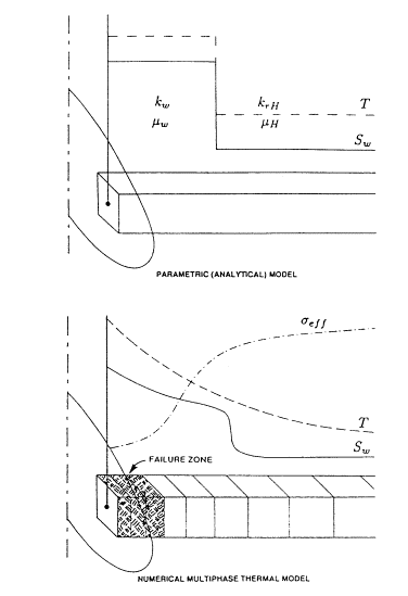
Two methods have been presented for modeling the change of physical parameters during injection (Figure 1). In the “parametric” or analytical leakoff model, the model assumes a one-dimensional piston-like displacement and describes the changes of physical parameters such as temperature, water saturation, relative permeability, etc, in the invaded region by their average. In the “numerical” leakoff model, the changes of physical parameters from each element of the fracture are computed by a one-dimensional (perpendicular to the fracture surface) finite difference model, which solves simultaneously for 2-phase flow, heat transfer and for the stresses.
Capabilities of the Model
Two-Dimensional Leakoff Correction
A 1-D leakoff assumption underestimates the leak-off, especially at low injection rates. Settari (1980)[5] introduced a correction factor to the 1-D leakoff velocity, which is a function of the dimensionless injection rate. Based on the results obtained from the Koning’s (1988)[6] model, a relationship is given between the correction factor and the dimensionless injection rate. This relationship shows that the 2-D leakoff correction can be several orders of magnitude different (Figure 2). This needs to be confirmed because this has a big effect on fracture size if this is true.
Figure 1. Two methods in handling the water invaded zone.
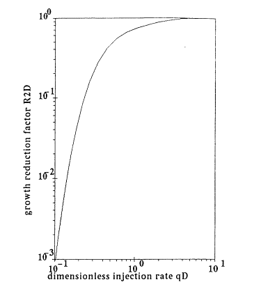
Figure 2. Leakoff correction factor due to 2-D flow.
Effects of Previous Injection
This is very important in studying falloff or step rate tests after a preceding period of injection. For example, previous injection leaves large pressure and saturation gradients in the fracture path, which will affect the leakoff rate. In the analytical model shown in Figure 1, since average values are used, this model does not account for pressure and saturation dissipation during shut-in. In the numerical model shown in Figure 1, leakoff, pressure, saturation and temperature are computed during shut-in periods and the solution therefore accounts for the dissipation process during shut-in.
Relative Permeability and Thermal Effects
Since water saturation is a function of position and, in many situations the average mobility has a minimum at an intermediate water saturation, effective mobility in the invaded zone may be considerably lower than the end-point values (see Figure 3). In the numerical model, since the saturation and relative permeability are modeling variables, this changing relative permeability can be accurately represented. The effective mobility in the invaded zone, which can be constructed by Welge’s tangent to the fractional flow curve, is at Sw= 0.5. Figure 3 shows that this value is much lower than the end-point values. It also should be noted that the mobility is temperature dependent.
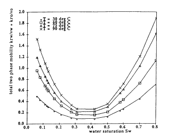
Figure 3. Total mobility in the invaded zone as a function of water saturation and temperature.
Pre-existing Propped/Acid Fractures
“When the pressure in the pre-existing (static) fracture increases during high rate injection, the closure stress on the fracture decreases, causing some increase of its conductivity. When the pressure reaches the confining stress, the entire fracture will unload (starting from the wellbore due to pressure losses) becoming part open and part propped fracture. Eventually, the dynamic fracture will start to extend from the tip of the static fracture.” 1
Pre-existing propped/acid fractures must be considered in modeling SRTs where pressure both below and at fracture conditions must be matched. The problem in modeling this process lies in how to model the combined conductivity of a static fracture and a dynamic fracture. Injection pressure can not be modeled by simply overlaying the static and dynamic fractures or just by considering either the static fracture or the dynamic fracture. A model is presented to represent the combined permeability (kf)c:
![]()
where kf = w2/12 is the permeability of the dynamic fracture with w being the fracture width and d is an input value of Dp at which the full permeability is reduced to one-half and Dp = poc (opening-closing pressure)- pf (computed pressure from the reservoir model). Figure 4 shows an example of using this approach to combine the static and dynamic fractures.
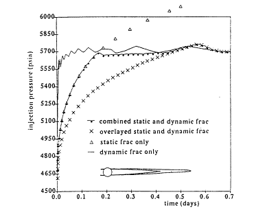
Figure 4. Simulated injection pressure with combination of static and dynamic fracture.
Field Study Methodologies
The proposed approach in analyzing field data can be broken into two phases – fracturing simulation and reservoir simulation. Basically, fracturing simulation determines fracture growth as a function of injection volume or time. Having developed a fracture growth versus time scenario with the fracturing simulator, the “description” of fracture and its conductivity is interfaced with a reservoir model to test the fracture growth versus time validity by comparing the computed injection pressures from both simulators. Injection pressure above fracturing can be matched by adjusting in-situ stress and net pressure. Pressure falloff can be used to determine net pressure and closure time. These can be history matched by adjusting leak-off and fracture volume. Ideally, the injection pressures from both fracturing and reservoir simulations should be the same by adjusting the input physical parameters. These adjustments should be determined from matching field injection history data and/or test data; such as step rate tests, falloff tests, hydraulic impedance tests. Usually the only parameters which need to be adjusted are those associated with leakoff rate in the fracture model.
A Case Study
An example has been published, showing how the model was used to reproduce step rate tests performed for well in Valhall field.1 Reservoir modeling of the SRTs is approached in a staged fashion. First, the pressure response due to injection below fracture was matched with a conventional reservoir model with a static fracture (if the well is so completed) by adjusting reservoir permeability and the static fracture conductivity. Matching the pre-fracturing data also provides for a point of departure between the observed and calculated pressure, which indicates when fracture starts.
A fracture description, generated with this matched permeability, is then interfaced to the reservoir model at the time of pressure departure. If the fracture extension is correct, the calculated injection pressure in the reservoir model will match the observed data. For example, if the calculated pressure is too low, then fracture growth rate needs to slow down in order to give a higher calculated pressure.
If a falloff test is available after the SRT, the pressure decline after fracture closure should also confirm the matched reservoir permeability.
[1] A. Settari and G.M. Warren, “Simulation and Field Analysis of Waterflood Induced Fracturing,” SPE/ISRM 28081, Eurorock 94 – Rock Mechanics in Petroleum Engineering, Delft, The Netherlands, August 29-31, 1994.
[2] A. Settari, G.M. Warren, J. Jacquemont, P. Bieniawski, and M. Dussaud, “Brine Disposal into a Tight Stress Sensitive Formation at Fracturing Conditions: Design and Field Experience,” SPE 38893, presented at the 1997 SPE Annual Technical Meeting, San Antonio, TX, October 5-8, 1997.
[3] “Fracture Propagation, Filter Cake Build-up and Formation Plugging During PWRI,” PWRI News Letter, Feature Article, Volume 1, No. 3, October 1999.
[4] J.E.V Ovens, F.P. Larsen and D.R. Cowie, “Making Sense of Water Injection Fractures in the Dan Field,” SPE 38928, presented at the 1997 SPE Annual Technical Conference and Exhibition held in San Antonio, Texas, 5-8 October 1997.
[5] A. Settari, “Simulation of Hydraulic Fracturing Processes,” SPE Journal, December 1980, pp. 487-500.
[6] E.J.L. Koning, “Waterflooding Under Fracturing Conditions,” PhD thesis, Technical University of Delft, 1988.
![]()
| <BP Multi-Lateral Spreadsheet | Hydfrac / Hydfrac V3> |