TerraFrac™
Basic Description of the Model1
TerraFrac™ is a PC-based hydraulic fracturing simulator based on fully coupled three-dimensional elasticity and two-dimensional fluid flow between fracture surfaces. Fracture growth is governed by fracture mechanics. The fracture is subdivided into discrete triangular elements by an adaptive meshing generator and the governing equations for these elements are solved by an approach similar to finite element method. That is, the modal force and displacement are related by a stiffness matrix. These governing equations consists of:
Thermoelastic and poroelastic effects are considered in the model. Elastic modulus contrast between layers and their effects on fracture growth are modeled. For long-term injection, fractures can cross many different zones and all or parts of the fracture can close during injection. The model can simulate fracture closure on part of the fracture and re-opening if pressure becomes high enough again during injection.
Adaptive Meshing Generator
In order to solve the governing equations numerically, the fracture must be subdivided into elements. For three-dimensional hydraulic fracture modeling, the fracture geometry must be determined during the simulation and can be very complex in shape. More importantly, the fracture constantly changes its shape during injection and therefore, the meshing generator must be adaptive.
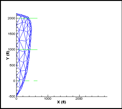
The meshing generator implemented in TerraFrac™ is based on DeLaunay triangulation. It has proven to be robust and adaptive for continuing fracture shape evolution. The following are three examples generated by the meshing generator.

Figure 1. A snap-shot mesh for a run-away.
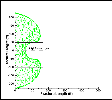
Figure 2. A snap-shot mesh for an hour-glass shaped fracture due to either high stress or a large permeability pay zone.
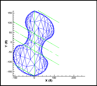
Figure 3. A mesh for a non-symmetric fracture in dipping strata.
Examples
Several example simulations are shown below. These examples show the mechanisms such as stress, permeability, elastic modulus, fluid viscosity, etc., that can affect the fracture geometry. All of the mechanisms interact together to govern the fracture geometry. For example, the example shown for high stress barriers (Figure 5) indicates that the fracture is contained by the high stress in the upper and lower zones. However, if the fluid viscosity were higher, the pressure drop from the wellbore to the fracture front in the lateral direction would be larger and the fracture could grow in the vertical direction, rather than laterally.
Contained Fracture Due To A Stress Barrier This case is for a contained fracture in a three-layered formation with uniform properties except for the minimum in-situ stress, as shown in Figure 4. The large stresses in the bounding layers prevent out-of-zone growth. If the frictional loss along the fracture becomes large either (due to large fracture length or due to higher fluid viscosity), then out-of-zone growth may occur. Selected simulation using TerraFrac™ is shown in Figure 5.
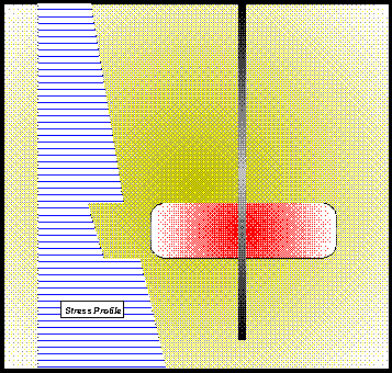
Figure 4. Stress profile and schematic of the expected fracture shape.

Figure 5. Large stresses in the upper and lower shales prevent the fracture from growing substantially out of the sand.
Circular Fracture
This is a classic simulation. There are even some closed-form solutions to restricted versions of this problem. The example shown here entails fracturing in a homogeneous, isotropic environment with only regular variation in the minimum horizontal stress (refer to Figure 6). Selected simulation using TerraFrac™ for this case is shown in Figure 7.
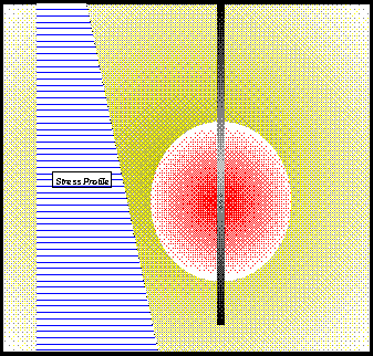
Figure 6. Stress profile and schematic of the expected fracture shape.
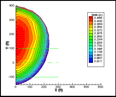
Figure 7. Fracture shape and fracture width contour plot for a "circular" fracture.
Multi-Layered Formations with Different Stresses
This case shows a fracture in a layered environment, with different in-situ stress levels in each of the layers; as shown schematically in Figure 8. Selected simulation results using TerraFrac™ are shown in Figure 9.
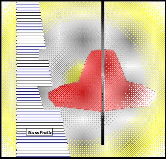
Figure 8. Stress profile and schematic of the fracture shape.
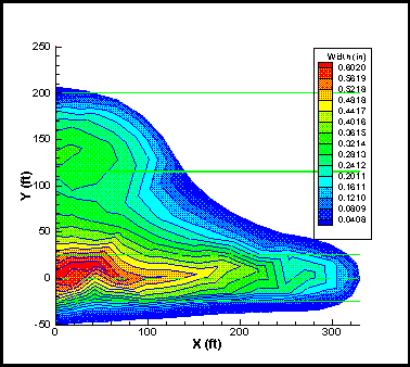
Figure 9. Fracture shape and width contour plots, at shut-in.
Fracture Containment Due To A Modulus Barrier
This case demonstrates the non-symmetric features (inclined) and the to fundamentally incorporate elastic moduli contrasts between layers. The example shown here is a three-layer scenario. The layers dip at 45o (for demonstration purposes only). The elastic moduli for the top and bottom layers are ten times the elastic modulus of the middle layer. Other properties for the three layers are the same. Figure 10 shows the fracture shape and width contours, at shut-in. As can be seen, fracture growth into the higher modulus layers is limited because of much smaller apertures and consequent larger pressure gradients.
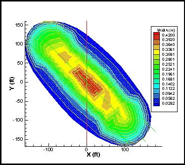
Figure 10. An elevation view of the fracture shape and width contours for a formation dipping at 45°, showing the elastic modulus effect on fracture growth.
A Leakoff Barrier
This example shows the effect of permeability and solid particles on fracture growth in drill cuttings re-injection. The fracture propagates rapidly upward due to lower in-situ stress at smaller elevations. As the fracture enters the upper zone, which large permeability, fluid leaks off into the formation and high concentration of solid particles prevents the fracture from growing up further, as shown in Figure 11. The same characteristic plugging effect can be anticipated for PWRI.

Figure 11. This case shows that the fracture is contained by a highly permeable sand during drill cuttings re-injection.
Hourglass-Shaped Fractures
This case was a three-layered situation with larger in-situ stresses (or large permeability) in the perforated, middle layer. As the fracture enters the upper and lower layers, which have smaller in-situ stresses, the growth rate into these two layers becomes larger and the fracture is pinched in the middle layer. An hourglass-shaped fracture is developed, as shown in Figure 12.

Figure 12. Hourglass shaped fracture and the fracture width contours.
Non-Symmetric Fractures
This example shows a non-symmetric fracture growing from an inclined wellbore and in three dipping layers, with larger in-situ stresses (or large permeability) in the perforated, middle layer. As the fracture enters the upper and lower layers, which have smaller in-situ stresses, the growth rate into these two layers becomes larger and the fracture is pinched in the middle layer, as shown in Figure 13.
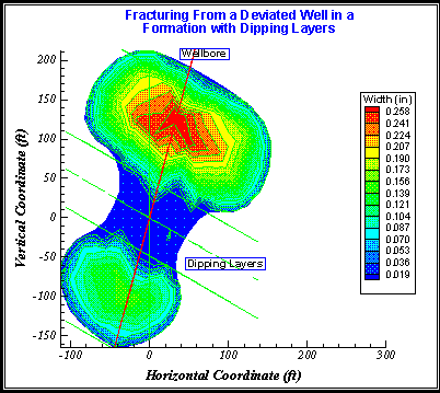
Figure 13. A non-symmetric fracture from an inclined wellbore in a formation with dipping layers.
1 R.J. Clifton, "Three-Dimensional Fracture-Propagation Models,", Chapter 5 in Recent Advances in Hydraulic Fracturing, SPE Monograph Vol. 2, edited by J.L. Gidley, S.A. Holditch, D.E. Nierode and R.W. Veatch, Jr.
![]()
| <Shell 2 | VISAGE> |
References
1. Cliford, P.J., Berry, P.J. and Gu, H.: "Modeling the Vertical Confinement for Injection Well Thermal Fractures," SPE 20741 (1990).
2. Martins, J.P., Murray, L.R., Clifford, P.J., McLelland, G., Hanna M.F., and Sharp Jr, J.W.: "Long-Term Performance of Injection Wells at Prudhoe Bay: The Observed Effects of Thermal Fracturing and Produced Water Re-Injection," paper SPE 28936, presented at the 1994 SPE (69th) Annual Technical Conference and Exhibition held in New Orleans, LA, September 25-28.
3. Clifford, P.J., Mellor, D.W. and Jones, T.J.: "Water Quality Requirements for Fractured Injection Wells," paper SPE 21439, presented at the 1991 SPE Middle East Oil Show held in Bahrain, November 16-19.
4. Settari, A. and Warren, G.M.: "Simulation and Field Analysis of Waterflood Induced Fracturing," paper SPE/ISRM 28081 presented at the 1994 Eurorock 94 - Rock Mechanics in Petroleum Engineering, Delft, The Netherlands, August 29-31.
5. Settari, A., Warren, G.M., Jacquemont, J., Bieniawski, P. and Dussaud, M.: "Brine Disposal into a Tight Stress Sensitive Formation at Fracturing Conditions: Design and Field Experience," paper SPE 38893 presented at the 1997 SPE Annual Technical Meeting, San Antonio, TX, October 5-8.
6. "Fracture Propagation, Filter Cake Build-up and Formation Plugging During PWRI," PWRI News Letter, Feature Article, Volume 1, No. 3, October 1999.
7. Ovens, J. Larsen, F.P. and Cowie, D.R.: "Making Sense of Water Injection Fractures in the Dan Field," paper SPE 38928 presented at the 1997 SPE Annual Technical Conference and Exhibition held in San Antonio, Texas, October 5-8.
8. Settari, A.: "Simulation of Hydraulic Fracturing Processes," SPE Journal, December 1980, pp. 487-500.
9. Koning, E.J.L.: "Waterflooding Under Fracturing Conditions," PhD thesis, Technical University of Delft, 1988.
10. Detienne, J-L., Creusot, M., Kessler, N., Sahuquet, B. and Bergerot, J-L.: "Thermally Induced Fractures: A Field Proven Analytical Model," paper SPE 30777 presented at the 1995 SPE Annual Technical Conference & Exhibition held in Dallas, Texas, October 22-25. 11. Perkins, T.K. and Gonzalez, J.A.: "The Effect of Thermoelastic Stresses on Injection Well Fracturing," SPE Journal, February 1985, pp. 78 - 88.
12. Morales, R.H., Abou-Sayed, A.S., Jones, A.H. and Al Saffar, A.: "Detection of Formation Fracture in a Waterflooding Experiment," paper SPE 13747 presented at the SPE 1985 Middle East Oil Technical Conference and Exhibition held in Bahrain, March 11-14.
13. R.J. Clifton, "Three-Dimensional Fracture-Propagation Models," Chapter 5 in Recent Advances in Hydraulic Fracturing, SPE Monograph Vol. 2, edited by J.L. Gidley, S.A. Holditch, D.E. Nierode and R.W. Veatch, Jr.
14. J. Ovens and H. Niko, "A New Model for Well Testing in Water Injection Wells Under Fracturing Conditions," SPE 26425, presented at the SPE 68th Annual Technical Conference and Exhibition held in Houston, Texas, 3-6 October 1993.