MWFlood
MWFlood is a pseudo-three-dimensional simulator for predicting the pressure and geometry of conventional hydraulic fractures associated with waterflooding. The program was specifically designed for evaluating the effects of injecting large fluid volumes over long periods and for fracture efficiencies approaching zero.
MWFlood has options for conventional (diffusion controlled) and steady-state (non-diffusion) fluid loss."At early times, fluid loss from the fracture is generally diffusion controlled, but at large times the fluid loss is governed by steady-state or pseudosteady-state leakoff. The fluid loss option has a marked effect on fracture geometry with larger leakoff rates at later times as compared to diffusion alone."
Features
Filtration Law
The Filtration Law has two options. Conventional is the standard diffusion type fluid loss model as used in MFrac. The Steady-State option is useful for long injection times when the leakoff rate is no longer controlled by diffusion but rather by steady-state injection and production.
The Conventional option is the standard type of fluid loss mechanism where the rate of fluid loss to the formation is governed by the total leakoff coefficient. This is referred to as diffusion type leakoff because the fluid loss mechanism is diffusion-controlled.
Steady-State
This option should be used for long periods of waterflood injection. The steady-state equations are based on the assumption that the production rate is equal to the injection rate resulting in a steady-state pressure behavior of the reservoir. [1]
Although steady-state fluid loss is not diffusion controlled at long injection periods, the leakoff velocity at early times is diffusion controlled (i.e. the leakoff velocity is inversely proportional to the square root of time). This option accounts for the fluid loss behavior changing from the conventional diffusion leakoff to a steady-state fluid loss controlled mechanism.
The resulting leakoff velocity for steady-state behavior approaches an asymptotic value. This results in a constant leakoff velocity since as time increases the fracture length asymptotes to a constant value.
Thermal Stress
The in-situ stress in MWFlood can be modified in the vertical and lateral directions to account for the effects of thermoelastic stresses. The fracture fluid temperature is specified by the user.
The thermal and water fronts are calculated based on the rate of creation of energy and mass. The fluid ahead of the thermal front is assumed to be at the reservoir temperature and the fluid behind the thermal front is at the fluid temperature specified for the fracture.
The injection fluid temperature is also used to calculate the induced thermoelastic stresses.Ahead of the thermal front, the stresses are equal to the initial formation stresses.
Behind the thermal front (and toward the wellbore), the modified stresses are seen by the fracture system.
The thermoelastic stresses perpendicular, D s T, to the major axes of the ellipse (fracture) are given by:
![]()
where:
b .................................................................... Thermoelastic Constant
a .......................................................... Coefficient of Thermal Expansion
D.......................... Temperature difference between fluid and reservoir (T1-Tf)
The thermoelastic stresses are determined for regions of elliptical cross sections and finite zone thickness (h) using the calculations by Perkins and Gonzalez. The thermal constant for stresses perpendicular to the major axes for (b1/h) < 0.01 is:
![]()
where b1 is the minor semi-axis of the elliptical thermal front perpendicular to the fracture and a1 is the major semi-axis of the thermal front (in the direction of the fracture length).
The limiting thermal constant for large minor axis to thickness ratios is unity (i.e., for b1/h > 10; b ®1.0). This condition generally occurs at later periods. Figure 1 shows typical Thermal Constant values for various thermal front conditions.
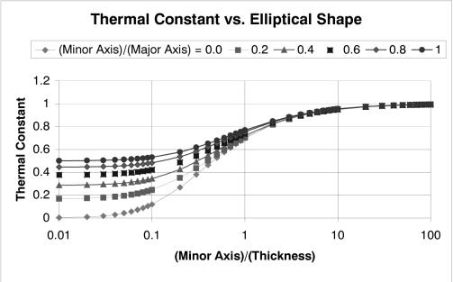
Figure 1. Thermal constant versus elliptical shape.
The modified stress is the minimum horizontal stress behind the thermal front (toward the wellbore). Ahead of the thermal front, the stresses are equal to the initial in-situ stresses.
The modified layer stress is equal to the initial layer stress, s, plus the thermoelastic stress, D sT,
![]()
where D s T is negative if the fluid injection temperature is less than the reservoir temperature.
Thermal/Water Front
The Thermal/Water Front input data include the oil displacement factor, the waterfront aspect ratio, the porosity, formation thickness and an equivalent drainage radius. This data are used to calculate the thermal front, waterfront, ellipsoidal waterflood shape, oil displacement and leakoff characteristics. The input data are:
Injected Fluid
The injected fluid represents the properties of the fracturing fluid. For waterflood applications, the user should specify water.
In-situ Fluid
The In-situ Fluid is the formation fluid that occupies the pores. Typically, this fluid is oil.
Oil Displacement Factor
The Oil Displacement Factor is the fraction of oil that is displaced by the water. This factor is directly related to the irreducible oil saturation (i.e., Oil Displacement Factor = 1- irreducible oil saturation).
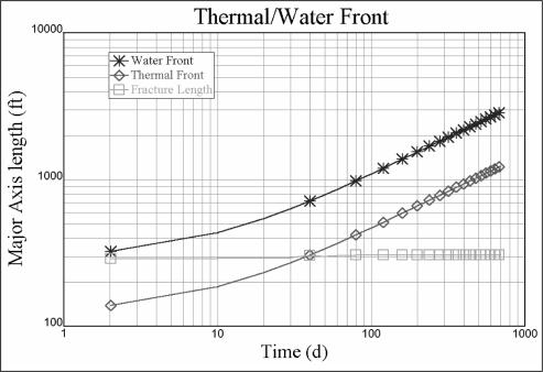
Figure 2. Flood and thermal fronts calculated for a specific situation using MWFlood.
Waterfront Aspect Ratio
This is the limiting aspect ratio of the minor to major axes of the ellipsoidal thermal and waterflood regions. The minor axis is perpendicular to the fracture plane and the major axis is in the fracture plane.
At early times, this aspect ratio is very large since it represents the fracture length divided by the leakoff distance perpendicular to the fracture face. Figure 3 illustrates that as time progresses this aspect ratio will decrease and asymptote to the user specified Waterfront Aspect Ratio.
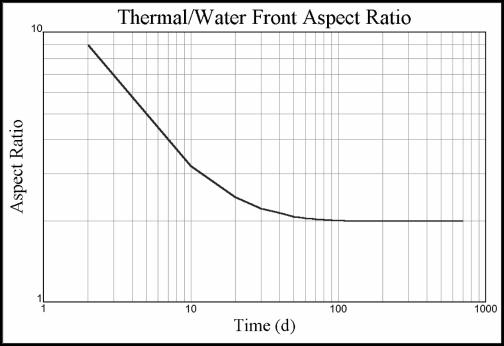
Figure 3. Thermal/Water Front Aspect Ratio as a Function of Time.
Formation Porosity
The formation porosity is the equivalent value over the fracture height used for calculating the thermal and waterflood regions.
The Net Formation Height is used in the mass conservation equations to calculate the water and thermal fronts. This height is also used for calculating the leakoff velocity for the Steady-State Filtration Law option.
Equivalent Drainage Radius
The equivalent drainage radius is used to calculate the steady-state leakoff velocity. The drainage radius is only used if the Filtration Law option is set to Steady-State.
[1] Note that the MWFlood documentation erroneously calls this pseudo-steady state. It is uncertain whether the formulation reflects this error, although the following paragraph suggests it does not.
![]()
| Hydfrac / Hydfrac V3> | Perkins and Gonzalez> |