What is a Drillstem Test (a DST)?
A DST is a temporary completion across the target zone. They are usually run in new wells but have been used in other situations. In this completion, the drillstring is the flow string. If the test is done correctly, you can get a sample of reservoir fluid (can be of value for compatibility evaluations), a measurement of static and flowing bottomhole pressure, and a short-term pressure transient test.
A DST is run on the drillstring to the zone of interest. The tools isolates the formation from the fluid in the annulus and allows formation fluid to flow into the drillpipe. A typical test involves the following cycles (numerous variations are possible):
1. A short production period.
2. A short shut-in period (the initial buildup).
3. A longer flow period (the second flow
period).
4. A longer shut-in (the final buildup).
Analysis
Usually, conventional Horner techniques can be used. During each shut-in, a Horner plot is done. Pressure is plotted against Horner time (a function of tp, the length of the flow period, and Dt, the time since the start of shut-in). Backwards extrapolation to a Horner time of 1 hour (p1hr) yields an estimate of reservoir (formation) pressure. Data from the first shut-in may be "overwhelmed" by storage effects. Potentially there is a predicted formation pressure for each shut-in. Skin can also be calculated for each shut-in. In general, a judgment will be made as to what are the most appropriate values for formation pressure and skin.
During each flow period, an average flow rate is determined. This can cause error for high productivity wells unless the well flows to the surface for a substantial portion of the flow period. As indicated, the flow rate of interest is an average rate. For a significantly variable rate:
![]()
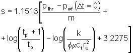
If the associated shut-in period is long enough and storage is not dominant, permeability can be estimated from a Horner plot for each cycle:
![]()
DSTs may report a damage ratio. This is:

The skin for each cycle is determined as:
Glossary and Other Parameters
Other parameters of concern for DST evaluation include:
Initial Hydrostatic Pressure: Initial hydrostatic head (psi, kPa, bar).
First Cycle Initial Pressure: Presuming an initial flowing period, as in a standard DST, this is the recorded bottomhole pressure at the start of the flow (psi, kPa, bar).
First Cycle Initial Time: The time at which the first flowing period started during a standard DST procedure (minutes, seconds)
First Cycle Final Pressure: Presuming an initial flowing period, as in a standard DST, this is the recorded bottomhole pressure at the end of the flow (psi, kPa, bar).
First Cycle Final Time: The time at which the first flowing period ended during a standard DST procedure (minutes, seconds).
First Cycle Closed Pressure: During a standard DST, after the first cycle, the tool is closed for buildup. This shut-in period is commonly 30 to 60 minutes in length, depending on the stabilization of the pressure. Stable bottomhole shut-in pressure is recorded. The value is in psi, kPa or bar.
First Cycle Closed Time: The time at which the first shut-in period ended (or at least when stabilized pressure is recorded) during a standard DST procedure (minutes, seconds).
Second Cycle Initial Pressure: Presuming a second flowing period, during a standard DST, this is the recorded bottomhole pressure at the start of the flow (psi, kPa, bar).
Second Cycle Initial Time: The time at which the second flowing period started during a standard DST procedure (minutes, seconds).
Second Cycle Final Pressure: Presuming a second flowing period, as in a standard DST, this is the recorded bottomhole pressure at the end of the flow (psi, kPa, bar).
Second Cycle Final Time: The time at which the second flowing period ended during a standard DST procedure (minutes, seconds).
Second Cycle Closed Pressure: Presuming a second flowing period, as in a standard DST, this is the stabilized recorded bottomhole pressure at the end of (or during) the shut-in (psi, kPa, bar).
Second Cycle Closed Time: The time at which the second shut-in period ended (or the pressure stabilized) during a standard DST procedure (minutes, seconds).
Third Cycle Initial Pressure: If a third flowing period is run, during a standard DST, this is the recorded bottomhole pressure at the start of the flow (psi, kPa, bar).
Third Cycle Initial Time: The time at which the third flowing period started during a standard DST procedure - if there is a third flowing period (minutes, seconds)
Third Cycle Final Pressure: Presuming a third flowing period, as in a standard DST, this is the recorded bottomhole pressure at the end of the flow (psi, kPa, bar).
Third Cycle Final Time: The time at which the third flowing period ended during a standard DST procedure (minutes, seconds).
Third Cycle Closed Pressure: Presuming a third flowing period, as in a standard DST, this is the stabilized recorded bottomhole pressure at the end of (or during) the shut-in (psi, kPa, bar).
Third Cycle Closed Pressure: The time at which the third shut-in period ended (or the pressure stabilized) during a standard DST procedure (minutes, seconds).
Final Hydrostatic Pressure: Final hydrostatic head (psi, kPa, bar).
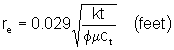
Radius of Investigation: This is an approximation of the radial extent of the reservoir that is affected during the test. One calculation procedure bases it on a dimensionless time of 0.25. This implies that:
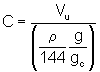
Wellbore Storage Coefficient: Wellbore storage is usually not significant in the buildup period of a DST. If data are unusual a log-log diagnostic plot may be necessary to determine what part of the data should be analyzed. Storage may be significant in thick sections. By definition, the wellbore storage coefficient is:
![]()
where:
DV .................. change in volume of fluid in the wellbore at wellbore conditions (bbl)
Dp ................................................................. change in bottomhole pressure (psi)
C ................................................................. wellbore storage coefficient (bbl/psi)
For a DST, this usually results from a rising liquid level in the drillpipe:
where:
Vu ............................................................ wellbore volume per unit length (bbl/ft)
r ........................................................................... wellbore fluid density (lbm/ft3)
g ............................................................................. acceleration of gravity (ft/s2)
gc ....................................................... units conversion factor (32.17 lbmft/(lbfs2)
The dimensionless wellbore storage coefficient is:
![]()
where:
CD ........................................................ dimensionless wellbore storage
coefficient
C ................................................................. wellbore storage coefficient (bbl/psi)
f ............................................................................................. porosity (fraction)
ct ................................................................................ total compressibility (psi-1)
h .................................................................................................. thickness
(feet)
rw ................................................................................... .
wellbore radius (inches)