Basic Description of the Model [1]
This model first considers the wellbore temperature profile as water flows down the injection string from the surface to bottom-hole. A linear geothermal gradient is assumed in calculating the temperature distribution along the wellbore. Thermal stress and poroelastic effects are considered in the model using the solution given by Perkins and Gonzalez.[2] Two-dimensional hydraulic fracturing model such as KGD is used in predicting fracture length and fracture width. Radial flow is considered before fracturing. Case studies are available to show the importance of thermally induced fracturing in water injection. Based on the model, the entire injection history can be divided into different regimes and the injection history over each regime can be matched with the model.
Capabilities of the Model
Wellbore Temperature Profile
The model first calculates the bottom-hole flowing temperature, using the surface temperature, the injection rate and the wellbore configuration. A linear geothermal gradient is assumed. The solution also assumes that the injection rate is constant. To cope with rate-varying behavior, an effective injection time has been used. It was found that as long as the injection rate does not vary too abruptly, the algorithm gives satisfactory results. This may explain the initial reduction in injectivity that is shown in Figure 1. As the bottom-hole flowing temperature decreases sharply initially (Figure 2), the average viscosity of the injected water increases and thus the injectivity decreases.
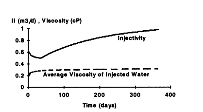
Figure 1. Injectivity index and viscosity.
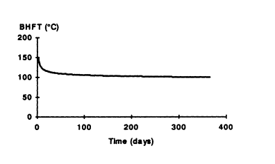
Figure 2. Bottomhole flowing temperature.
Radial Injection
The model calculates the bottom-hole flowing pressure by first assuming radial, matrix injection. It then tests whether this assumption is acceptable using a fracture criterion. If radial injection is acceptable, the model concludes that radial injection prevails and the model proceeds to the next time step. If the fracturing criterion is satisfied, strictly radial injection does not occur and the model calculates bottom-hole flowing pressure assuming that the reservoir has been fractured.
A conventional three-zone model is used for computing the flowing pressure during radial injection. For injection of a cooler fluid, there are: (1) a cooled-and-flooded zone from the wellbore out, (2) followed by a flooded zone, but with reservoir temperature and (3) finally the undisturbed virgin reservoir (see Figure 3).
For the cooled-and-flooded zone, viscosity is determined from correlations at different salinities and temperatures. Relative permeability is entered as data. For the flooded zone at reservoir temperature, the viscosity also comes from correlations. Relative permeability to hot water is also entered as data. Finally, for the undisturbed virgin zone, the viscosity and relative permeability are entered as data.
Determining the extent (size) of the cooled-and-flooded zone can be found in many papers.[3] However, all solutions assume injection of water at a constant bottom-hole flowing temperature. In reality, the bottom-hole injection temperature is changing, particularly in the early stages. The bottom-hole injection temperature as a function of injection time can be modeled. A concept based on average temperature is used in the model to include temperature changes.
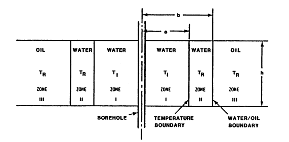
Figure 3. Temperature and water saturation profiles due to cold water injection as simplified three-zone model.
Thermal Stress and Poro-elastic Effects
It has been observed that injectivity which is lost on conversion from seawater to produced water can often be fully restored on conversion back to seawater. 2 Including thermal and poroelastic effects is important for correct analysis of such cases. Thermal stresses have been proven to be an important factor in modeling long term injection such as waterflood. Thermal stress due to temperature change during injection are estimated in the model according to the method proposed by Perkins and Gonzales. 2
The stress change due to poro-elastic effects is divided into a global reservoir effect and a local well effect. Each can be computed analytically.
Fracture Injection
After a fracture has been initiated, the fracture length and width are determined using a two-dimensional hydraulic fracturing model. An equivalent radius is used to represent the fracture in the injectivity index equation. This equivalent radius is based on skin calculation, which consists of geometric skin due to the fracture, filter cake skin, and skin due to damage. Skin is converted into an equivalent well radius. This equivalent well radius is then used for injectivity index calculation.
A Case Study
One case study has been published for an offshore oil field in West Africa. Ten wells have been injecting for a period of 3 to 5 years. Well head pressure has remained fairly constant at 100 to 120 bars. Typical initial injection rates were 200 to 800 m3/d. Typical increases in injectivity indices due to thermally induced fracturing are a factor of 1.5 to 2, bringing injection rates to the 1000 to 2000 m3/d ranges. On three wells, the injectivity indices increased by a factor 10.
Pressure Matching
Wellhead pressure was held constant at 120 bars. After 40 days of injection, injection rate increased abruptly from 200 m3/d and reached 2000 m3/d after 120 days. The radial flow model can correctly matches the wellhead pressure during the first 30 days (see Figure 4). If thermally induced fracturing is assumed at the point when the injection rate increased abruptly, the match of the radial injection regime during the first 30 days is unchanged. Now however, well history between 30 days and 60 days is reproduced as shown in Figure 5.
From this exercise it is concluded that:
Ø From 0 to 30 days, injection is in the radial injection regime.
Ø From 30 to 60 days, injection is in thermally induced fracturing regime.
At around day 60, the injectivity again suddenly increased. It was impossible to match the well behavior beyond 60 days with any reasonable set of reservoir parameters. One explanation offered was vertical fracture growth. The wellhead pressure and injection rate can be matched beyond 60 days by increasing the fracture height and reservoir permeability. It was found that in order to match the injection history, the fracture height had to be increased drastically from some 20 meters to 120 meters and later back down to 80 meters. With this increase and decrease of fracture height, the entire injection history (over 1200 days) can be matched by the model (Figure 6). But, as Detienne et al. 1 pointed out, there are no limits to the possibility of matching when k and h are allowed to vary from one time step to the next. A true 3D hydraulic fracturing simulator may be required to simulate this sudden fracture height growth and constrain the otherwise arbitrary variation of fracture height.
One feature which may also explain the observed phenomena can be secondary fractures due to stress orientation change resulted from thermal stress because thermal stresses in the directions parallel and perpendicular to the fracture direction are different, as indicated by Perkins and Gonzalez. 2
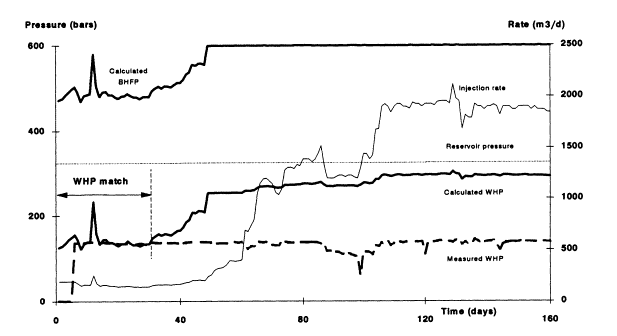
Figure 4. Attempt to match assuming radial flow.
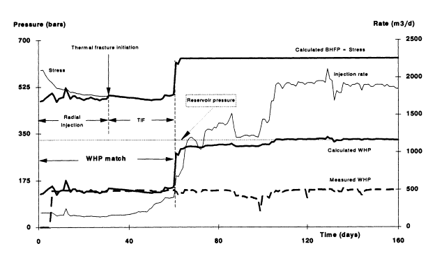
Figure 5. Attempt to match assuming TIF is confined vertically.
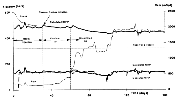
Figure 6. Final history match assuming an unconfined fracture.